
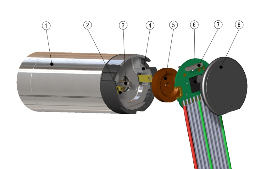
- ① Motor
- ② Motor terminal
- ③ Motor shaft
- ④ Magnetic shield
- ⑤ Magnetic wheel
- ⑥ IC
- ⑦ MR sensor
- ⑧ Cap
Rotary Encoder

Magnetic Encoder
Based on the concept of "ultra-small size (φ13, 16) and high performance", a magnetic rotary encoder allows a wide range of resolution to be selected by multiplying the signals detected by the MR sensor developed by our own technology with an IC. By integrating with the motor, 3 channels, high resolution, and voltage differential output have been realized in spite of being ultra-small (MR-13, MR-16).
It can be combined with Φ13, 16 and 17 coreless motors.
A magnetic rotary encoder that features ultra-small (φ8, 10, 13), 2 channels, and low pulse, and enables downsizing of the customer-designed housing by extending the lead wire in the axial direction. (MR-8, MH-10, MRS13)
It can be combined with φ8, 10 and 13 coreless motors. We have newly developed a φ8 magnetic encoder for a wider range of applications from the previous φ8 and 10 series.
Optical Rotary Encoder
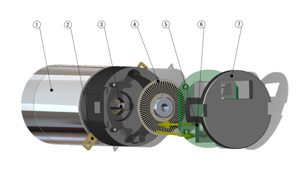
A rotary encoder that uses a reflective type equipped with a light-receiving and light-emitting element and a code wheel, and enables downsizing of the customer-designed housing by extending the lead wire in the axial direction. Since it is an optical type, it can be used even in a magnetic field environment (MK-16). It can be combined with a coreless motor larger than φ16.
| Rotary encoder Model | Magnetic | Optical | ||||
|---|---|---|---|---|---|---|
| MR-8 | MH-10 | MR-13 | MRS-13 | MR-16 | MK-16 | |
| Diameter | φ8 | φ10 | φ13 | φ13 | φ16 | φ16 |
| Channel | 2ch (A,B) | 2ch (A,B) | 3ch (A,B,Z) | 2ch (A,B) | 3ch (A,B,Z) | 2ch (A,B) |
| Resolution | 12P/R | 12P/R | 32~256P/R | 16P/R | 64~512P/R | 36~200P/R |
| Maximum response frequency | 20kHz | 20kHz | 80kHz | 20kHz | 160kHz | 30,60kHz |
| Output signal | TTL Compatible | TTL Compatible | Voltage differential TTL Compatible |
Voltage differential TTL Compatible |
TTL Compatible | TTL Compatible |
Magnetic encoder
Optical encoder
- ① Code wheel
- ② Motor shaft
- ③ Light emitting element
- ④ Light receiving element
Incremental
Rotary encoder oiuputs pulse signals in proportion to the amount of rotation.
It can be detected by counting the number of pulses from any reference position. The direction of rotation also can be detected by a phase difference (lead, lag) of A and B phases.
MR (Magnetic-Resistance) sensor
A sensor that utilizes a magnetic-resistance (MR) element that changes in resistance according to changes in the magnetic field strength.
Resolution (P/R)
The number of pulses of signals output from rotary encoder per revolution of the motor shaft. As the resolution becomes higher, finer control becomes possible.
Output signal
Phase A : Square wave signal output by the number of resolution.
Phase B : A signal having a phase difference from Phase A and is capable of detecting a direction of rotation by its difference (lead and lag).
Phase Z : Outputs one pulse per revolution (for origin detection).
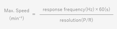
Maximum response frequency
Maximum signal per second that rotary encoder can be response. The maximum Speed, resolution and maximum response frequency are related to each other as expressed by the following equation:
TTL
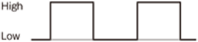
TTL:Transistor Transistor Logic
Output by square waves of High (2.4V or over) and Low (0.4V or below).
Voltage differential
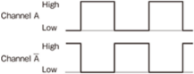
Noise-caused disturbances can be reduced because two signals having a 180-degree phase difference from each output are output (differential output).