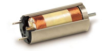
♦ The micro DC coreless motors are "small and high-performance" series motors realized by advanced precision machining technology and original winding technology that offer high outputs and controllability.
♦ In addition to the existing f 12 - 17.55 series, f 10, f 21 and f 24 coreless motors have been developed for use in wider applications.
♦ Our coreless motors have lower rotor inertia than that of DC iron core motors, the response is superior. Also due to no cogging, vibration and noise are smaller to offer better controllability.
♦ A wide variety of combination with magnetic/optical rotary encoders and various gearheads are possible for our coreless motors.
♦ Our coreless motors are able to design Custom-tuned specifications for brush materials, winding, ball bearings, etc.
|
|
|
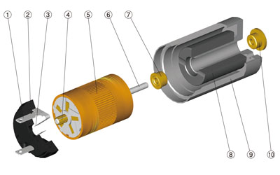
Coreless motor (1) Terminal (2) Brush base (3) Brush (4) Commutator (5) Coil (6) Shaft (7) Bearing (8) Magnet (9) Housing (10) Bearing |

|
|
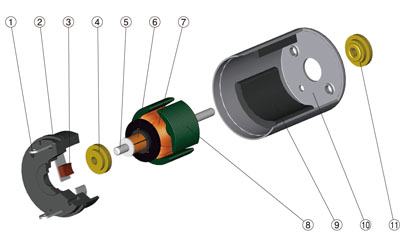
Iron core motor (1) Terminal (2) Brush base (3) Brush (4) Bearing (5) Shaft (6) Commutator (7) Coil (8) Iron core (9) Magnet (10) Housing (11) Bearing |

|
♦ Rated voltage[ V ]
A voltage that is required to run a motor at the rated load and rated speed. (A voltage when applied to between DC motor terminals.) The rated voltage to use must be ± 10% of the marked voltage. (Please contact us for use outside this range.)
♦ No-load speed[ min-1 ]
Speed per minute when a motor is run at the rated voltage under no load.
♦ No-load current[ mA ]
A value of current when a motor is run at the rated voltage under no load.
♦ Starting torque[ mNm ]
Maximum current that flows at the rated voltage when a DC motor is started or locked.
♦ Starting current[ mA ]
Maximum current that flows when the rated voltage is applied.

♦ Output[ W ]
The DC motor output can be calculated by the following equation:

♦ Maximum efficiency[ % ]
The maximum value of the input-to-output ratio.
♦ Terminal resistance[ O ]
Resistance between winding/brush and commutator/terminal or lead wire. A value of resistance measured between terminals of a DC motor. In the case of the graphite brush, the resistance changes according to current.
♦ Rotor moment of inertia[ gcm2 ]
Moment of inertia of the mass of the rotor.
♦ Rotor inductance[ mH ]
An approximate value measured between terminals of a DC motor with a measuring frequency of 1 kHz.
♦ Torque constant[ mNm/A ]
Torque that occurs when current is 1A.

A voltage that is required to run a motor at the rated load and rated speed. (A voltage when applied to between DC motor terminals.) The rated voltage to use must be ± 10% of the marked voltage. (Please contact us for use outside this range.)
♦ No-load speed[ min-1 ]
Speed per minute when a motor is run at the rated voltage under no load.
♦ No-load current[ mA ]
A value of current when a motor is run at the rated voltage under no load.
♦ Starting torque[ mNm ]
Maximum current that flows at the rated voltage when a DC motor is started or locked.
♦ Starting current[ mA ]
Maximum current that flows when the rated voltage is applied.

♦ Output[ W ]
The DC motor output can be calculated by the following equation:

♦ Maximum efficiency[ % ]
The maximum value of the input-to-output ratio.
♦ Terminal resistance[ O ]
Resistance between winding/brush and commutator/terminal or lead wire. A value of resistance measured between terminals of a DC motor. In the case of the graphite brush, the resistance changes according to current.
♦ Rotor moment of inertia[ gcm2 ]
Moment of inertia of the mass of the rotor.
♦ Rotor inductance[ mH ]
An approximate value measured between terminals of a DC motor with a measuring frequency of 1 kHz.
|
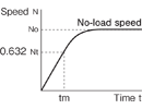
♦ Mechanical time constant[ ms ] A constant (tm) that indicates a time required by the DC motor from rising from the rest state to reaching 63.2% of the no-load Speed. |

|
Torque that occurs when current is 1A.

|
♦ Winding allowable temperature[ °C ] Winding employed is insulating heat-resistant type B (130°C). If you need special heat resistance, please contact us. |

|


