


| Magnetic
Encoder |
Optical rotary encoder | ||
|
♦ ♦ ♦ ♦ |
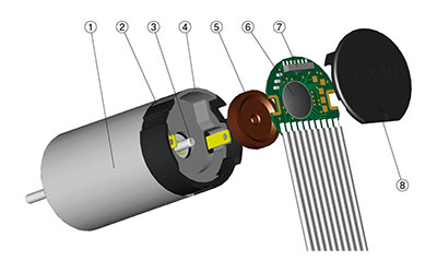
The MR sensor and ASIC developed by the original technology based on the concept of "very small and high
performance" are employed. (MR-13 andMR-16, magnetic rotary encoder) wide range resolution can be selected by multiplying signals detected by the MR sensor via the ASIC. (MR-13 and MR-16, magnetic rotary encoder) As designed in one unit with a motor, these magnetic rotary encoders are very small, yet offer such features as 3 channels, high resolution and line driver outputs. (MR-13, MR-16) Magnetic rotary encoder which can be wide variety of combination with coreless motors is possible. |
♦ ♦ |
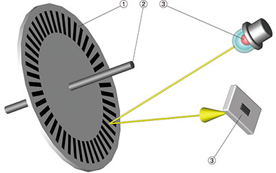
A reflective encoder carrying light emitting and receiving elements and code wheel. Optical type rotary encoder can be use in a magnetic environment. |
| Rotary encoder Model | Magnetic | Optical | ||
| MH-10 | MR-13 | MR-16 | ME-16 | |
| Diameter | f10 | f13 | f16 | f16 |
| Channel | 2CH (A,B) | 3CH (A,B,Z) | 3CH (A,B,Z) | 2CH (A,B) |
| Resolution | 12 P/R | 32-256 P/R | 64-512 P/R | 75-200 P/R |
| Response frequency | 20 kHz | max.80 kHz | max.160 kHz | 60 kHz |
| Output signal | TTL | Line Driver (TTL) | Line Driver (TTL) | TTL |
|
Magnetic encoder (1) Motor (2) Motor terminal (3) Motor shaft (4) Magnetic shield (5) Magnetic wheel (6) ASIC (7) MR sensor (8) Cap |
|
|
Optical encoder (1) Code wheel (2) Motor shaft (3) Light emitting element (4) Light receiving element |
|
♦ Incremental
Rotary encoder oiuputs pulse signals in proportion to the amount of rotation.
It can be detected by counting the number of pulses from any reference position. The direction of rotation also can be detected by a phase difference (lead, lag) of A and B phases.
♦ MR (Magnetic-Resistance) sensor
A sensor that utilizes a magnetic-resistance (MR) element that changes in resistance according to changes in the magnetic field strength.
♦ Resolution (P/R)
The number of pulses of signals output from rotary encoder per revolution of the motor shaft. As the resolution becomes higher, finer control becomes possible.
♦ ASIC
The ASIC (custom IC) specially designed for CITIZEN MICRO's rotary encoders. Very small, yet such features as 3 channels, line driver and high resolution have been realized.
♦ Output signal
Phase A : Square wave signal output by the number of resolution.
Phase B : A signal having a phase difference from Phase A and is capable of detecting a direction of rotation by its difference (lead and lag).
Phase Z : Outputs one pulse per revolution (for origin detection).
♦ Maximum response frequency
Maximum signal per second that rotary encoder can be response. The maximum Speed, resolution and maximum response frequency are related to each other as expressed by the following equation:
|
♦ TTL TTL:Transistor Transistor Logic Output by square waves of High (2.4V or over) and Low (0.4V or below). |
|
|
♦ Line driver Noise-caused disturbances can be reduced because two signals having a 180-degree phase difference from each output are output (differential output). |
|