Control by resistance
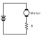
A resistor is placed in series between the power supply and the DC motor for restricting current by an increase in resistance to control the motor speed. The use of a variable resistor can vary the motor characteristics linearly control.
Braking (Short-circuit brake)
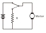
A method to force the terminals of the DC motor to be shorted to stop the motor. This method can shorten the stopping motor time and provides powerful braking control. (Maximum braking when R = 0)
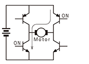
Bidirectional driving of DC motors by transistors
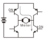
Bidirectional motor driving is achieved by switching the H-type bridge circuit by use of NPN and PNP transistors.
PWM control (pulse width modulation method)
The basic principle is to change the average energy and control the speed by changing the ratio of "ON" and "OFF" of the pulse with a constant cycle. There is also a method that uses a transistor (a control method called switching drive or chopper drive), but it is common to use the PWM method for the motor.
The ratio of ON and OFF of the applied voltage is called the duty ratio, and the speed is controlled by varying the average voltage applied to the motor by that ratio.
For example, comparing (a) and (b), the driving energy is larger in (b) which has a higher duty ratio. If the duty ratio is 50% (the ratio of ON and OFF is the same), the speed is halved.

Electric Noise Measures
When a DC brush motor rotates, spark current occurs due to switching of the commutator. This spark may become electric noise to adversely affect the control circuit. Such noise can be reduced by connecting a capacitor to the DC motor case. (Note, however, when the motor is PWM-controlled, the frequency characteristics must be examined.)


